New high speed cameras and very energetic test instruments produce test results that are amazing and unexpected. It’s an exciting time to be doing high strain rate material testing!
Most tensile, shear and compression experiments are performed slowly under quasi-static conditions. This means that the acceleration effect on load measuring devices is insignificant and the stress wave propagation in the test specimen need not be considered. The strain rate of typical quasi-static tensile tests is between 0.001/s and 0.01/s.
Testing at slow speeds has been possible for a long time. The region of interest here is the 1/s to 1000/s strain rate range. This range of testing covers metal forming, car crashes, cell phone drops and other issues of practical importance. And we’re learning that one can’t test at very slow speeds, very high speeds and interpolate between.
About strain units: 1/s = 100% per second. Or another way to think about this is 1/s means a 10 mm section stretches to 20 mm in 1 second. 1000/s means a 10 mm section stretches to 20 mm in 0.001 second.
Elastomers generally become stiffer with increased strain rate. Some engineering plastics exhibit almost no initial stiffness sensitivity but do exhibit significant yielding and failure behavior changes. Polymer composites may show different failure mechanisms at different strain rates.
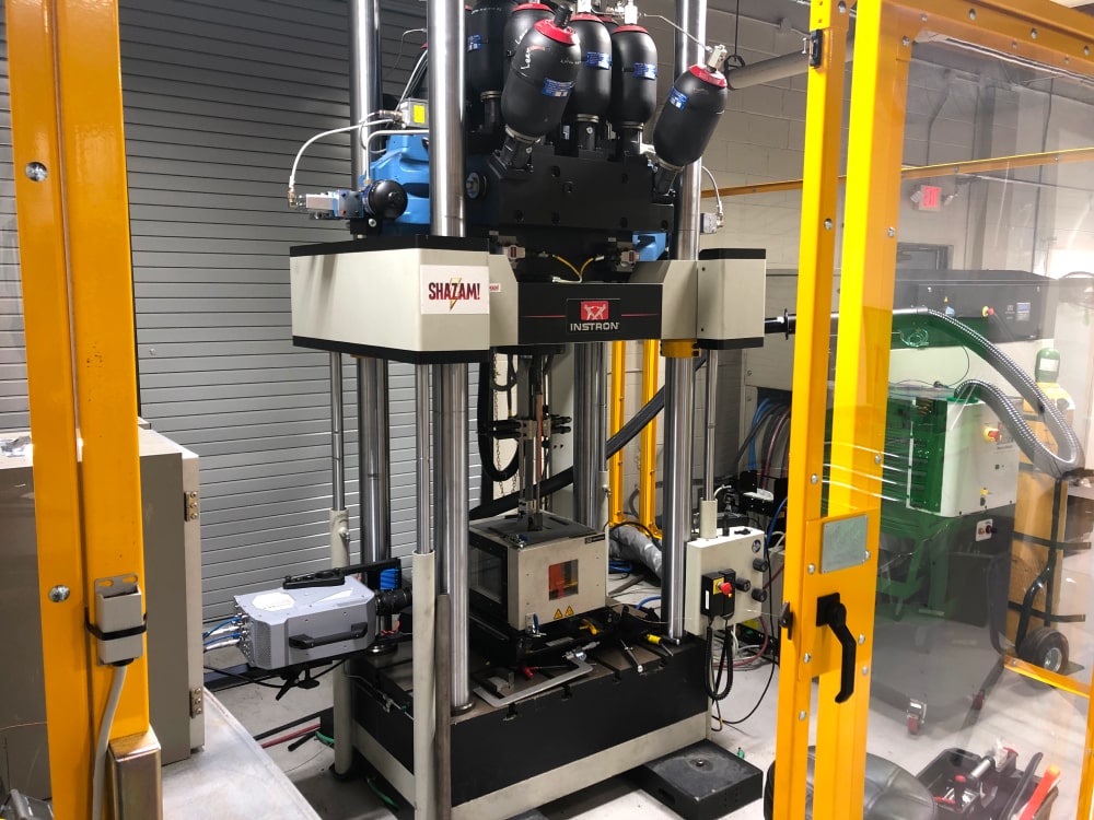
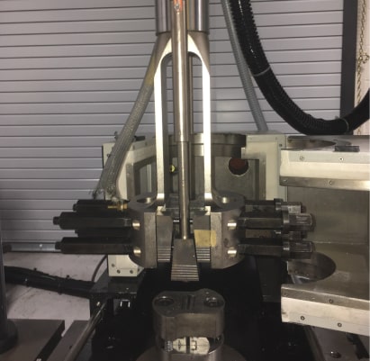
Instron VHS 160/100-20 High Strain Rate Test System with Photron Camera and Chamber
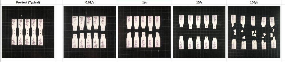
ISO 8256 Type 3 Tensile Test Specimens From Left to Right: Untested, Tested at 0.01/s, Tested at 1/s, Tested at 10/s and Tested at 100/s
The Loading System
A loading system is required to deform the test specimen.
For quasi-static tests, this is typically an electromechanical test instrument that uses a screw driven crosshead to apply a constant rate of deformation. To achieve higher strain rates, the loading system needs to be able to move faster. A faster loading system such as a servo–hydraulic or electro-dynamic test instrument may be necessary.
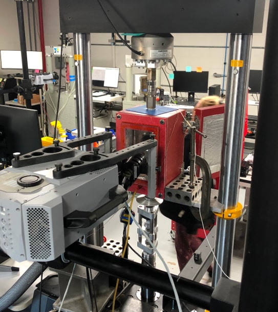
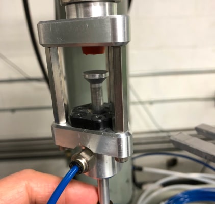
Medium Strain Rate Tensile Test Instrument with Photron SA-Z Camera and Slack Grip System
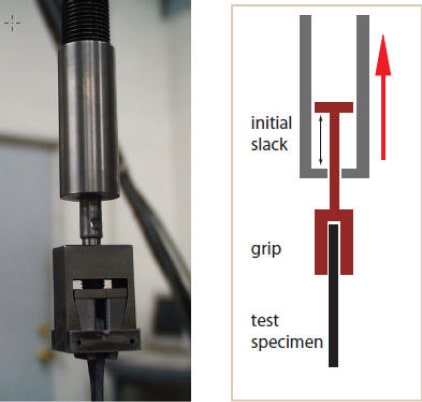
High Strain Rate Testing: Gripping System with Slack
It is important that the instrument achieves the desired strain rate quickly. If this isn’t possible yet the instrument is still capable of the needed test speed, a slack grip system may be used. A slack grip system allows the loading system to ramp to the needed test speed prior to engaging the test specimen. A simple system may allow motion before 2 surfaces make contact and engage the specimen grip. We have several varieties of this for different force and load cases.
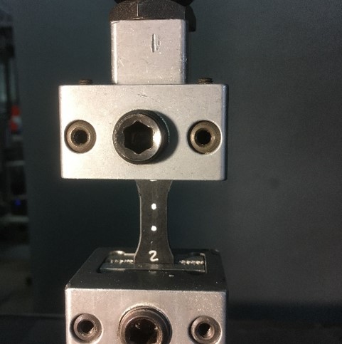
A very advanced system that we have at Axel for high-speed, high-energy tests employs a system that “grabs” a moving piece after the desired velocity is achieved. This avoids a “bounce” in the slacking system. This is a commercial product made by Instron Corporation called a FastJaw.
Basic Slack Schematic and Image
Instron FastJaw Slack System
Low Mass Slack System
Strain Measurement
The strain in the test specimen needs to be measured on the surface of the test specimen.
Optical methods are almost always used. At Axel, we have several Photron high speed cameras and a wide variety of medium speed cameras and lighting systems. Cameras, lighting, lenses and triggers are the working tools of high speed testing.
With a Digital Image Correlation (DIC) processing technique, a strain field on the surface of the test specimen is calculated. A randomized pattern is applied to the specimen surface and the collected images are processed to extract straining in a selected region. This is a powerful approach that allows us to observe transverse strains and highly localized strain regions.
A simpler and often more pragmatic solution is to track 2 dots or markers on the test specimen.
Tensile Specimen with Strain Tracking Dots
Tensile Specimens Prepared for High Strain Rate Testing. Some Have Dots for Strain Tracking. Some Have a Speckle Pattern for DIC Post Strain Analysis
Adhesive Lap Shear Experiment for a 100/s Strain Rate Test. A Photron Nova Camera, Piezo and Strain Gauge Force Cells and Slacking System are Ready
High Strain Rate Testing: Force Measurement
A force measuring transducer is used to measure the force transmitted through the test specimen.
For quasi-static tests, this transducer is typically a strain gauge based load cell. Strain gauge based load cells are too soft at higher strain rates because they introduce inertial effects and free vibrations in the time frame of interest. Piezoelectric force sensors that are significantly stiffer are used. These sensors drift over time and are generally nota good choice for quasi-static tests. In addition to a stiffer load cell, the mass of the test specimen grip that rides on the load cell needs to be reduced to minimize inertial loading from the grip.Another option is to strain gage the specimen grip such that it also acts as a load measuring device.
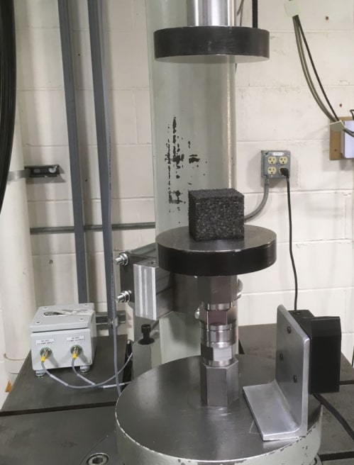
A EPP Foam Block is Positioned for High Strain Rate, High Energy Compression